If an operatorAn entity or organization responsible for the operation, management, and maintenance of a pipeline system. The operator is entrusted with ensuring the safe, rel… invests in an inspectionThe systematic process of visually examining, testing, or monitoring pipeline components to assess their condition, integrity, and compliance with regulatory re… with two, or even three of all of these solutions, a complete and accurate model is born. This provides insights based on facts, ridding interpretations and oversimplifications that the common approach ignores.
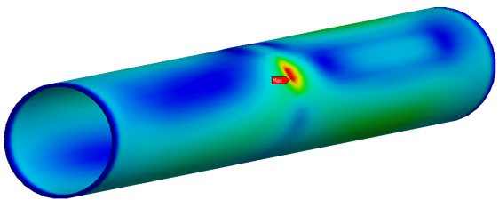
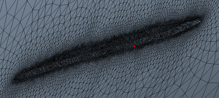
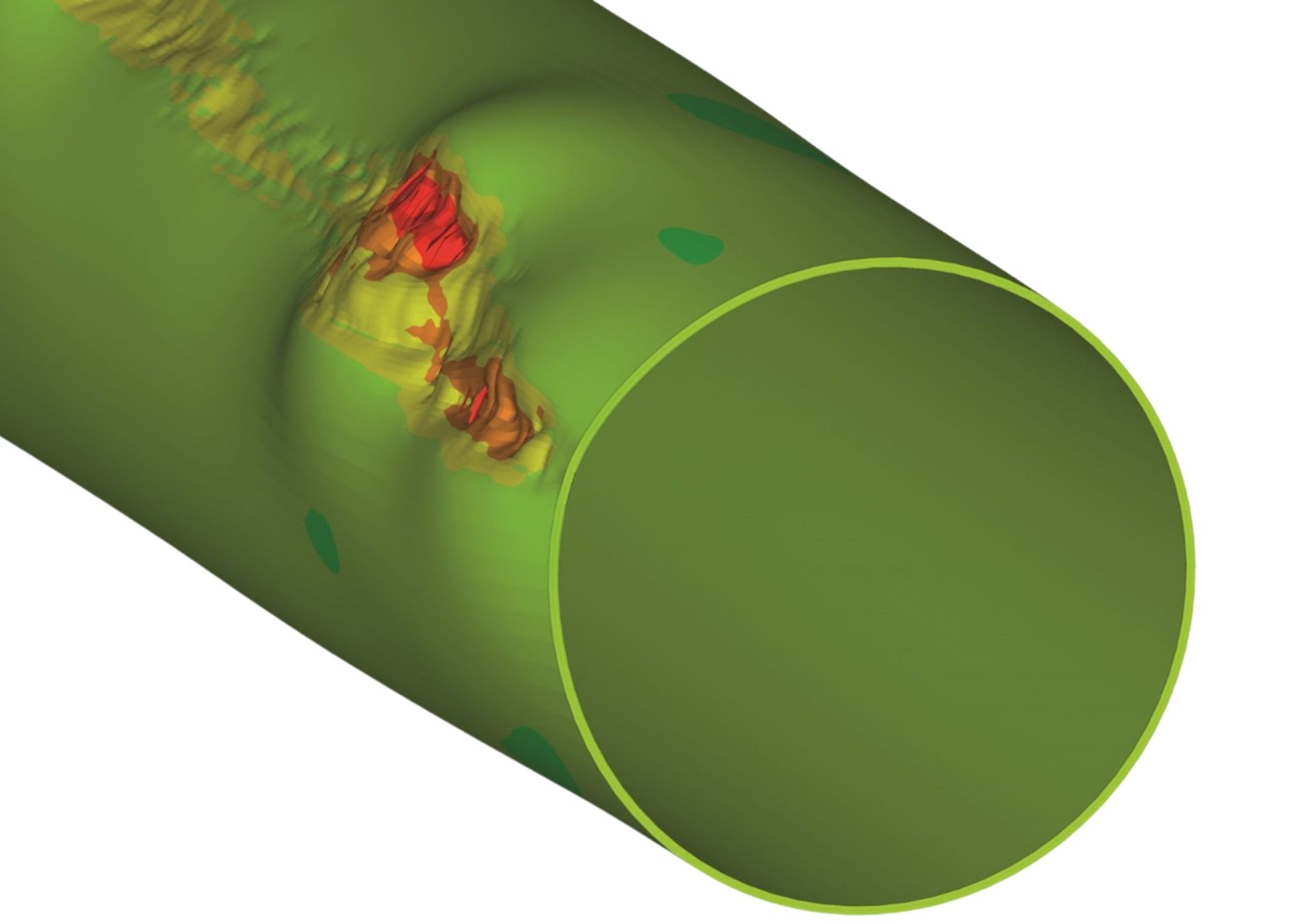
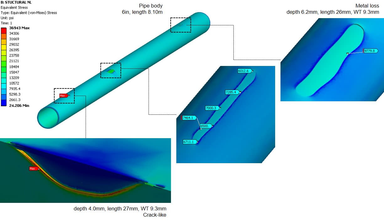
Figure No. 1 on the left is an FEA visualization: a model of a pipe jointA single section (also pipe spool) of pipe that is circumferentially welded to form a pipeline. that incorporates wall thickness readings, real pipeline geometry and crackA fracture or discontinuity in the wall of a pipeline, where the material is separated or broken, potentially compromising the integrity and safety of the pipel…-like features. The image visualizes the results of a combined technology inline inspectionA method used to assess the the integrity and condition of pipelines. It involves the use of specialized tools that are inserted into the pipeline and propelled…: a complete joint (spool) incorporating the most realistic pipe geometry, accurate wall thickness measurements and crack defects that include depth profiling. The results can then be understood in terms of failureThe inability of a pipeline system to fulfill its intended function or meet the required performance criteria. Pipeline failures can have significant consequenc… pressures, combined stresses, remaining lifeThe estimated duration that a pipeline is expected to remain in service before it reaches the end of its operational life. This estimate is based on various fac…, and future and fatigueThe process where cracks develop and propagate in a material under cyclic loading or repeated stress over time. It is a type of fatigue failure that occurs when… life.
Included in this visualization is a model predicting pressure scenarios and includes inputs such as cycle changes and hydrotest pressures. In conclusion, to leverage an FEA in the most accurate way possible, assessments should be conducted be highly skilled engineers who can both understand the data and can properly handle the data from beginning to end.
For best results, Finite Element Analysis should incorporate a combination of datasets from multiple runs and provide insights from complex data so operators can receive results that are precise and truly applicable to their integrity management programA documented set of policies, processes, and procedures implemented by operators to ensure the safe, reliable, and efficient operation of pipelines throughout t….


